Tunnel Animation
I was provided with an image of a tunnel and an animated camera. I had to make it look like the camera was moving through the tunnel.

First I created a cylinder and rotated it 90 degrees. I then changed the Y scale to 200. I connected this to the image.

I then connected the cylinder to a scene node and then connected that to a scanline render node. I also connected the camera to the scanline render node. However, the imaged was stretched.

To fix this I added a project 3D node between the image and the cylinder. I then connected a framehold node to the camera and set it to frame 1001. Then I connected the framehold node to the project 3d node.

Final Video

Tunnel Animation
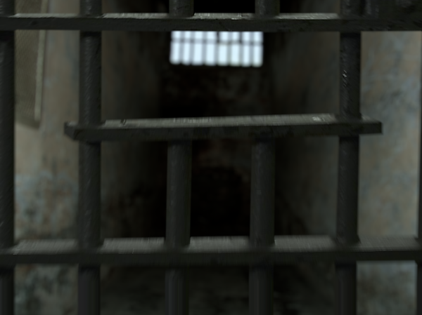
I was provided with four images of a jail, one image of jail bars and two cameras. One of the cameras was animated and the other one was still. I had to project the images onto the cards.

I started with the back wall. First I added a copy node and then connected the B pipe to the image and the A pipe to a roto node. I also connected the output pipe to a premult node. I then roto'd around the back wall. I added a blur node to feather the edges.

I then added a project 3D node and connected the camera input to the projection camera. Next, I added a card node and went into 3D mode. I adjusted the position and scale of the card so that none of the image was getting cut off. I then connected the card node to a scanline render node and connected the cam input to the animated camera.

After that, I did the same thing for all of the other images and merged them all together. I didn't need to roto the bars because it already had an alpha channel.

Finally, I added some effects to make it look better. I added an edge blur on the walls to make them blend in better. I also added a defocus node for the bars and another one for everything else so I could control what was in focus. Another thing that I did was I changed the samples on the scanline render for the bars to 5 to create some motion blur.
Final Video

Nuke 3D Tracking
For this exercise, I was provided with a nuke file which included a video of a boat going along a river. It also had a node set up to undistorted and then re-distort it again. I had to remove the windows on one of the buildings.

First I added copy node. I connected the B pipe to the undistorted footage and connected the A pipe to a roto node. I then roto'd around the areas that I didn't want to be tracked.
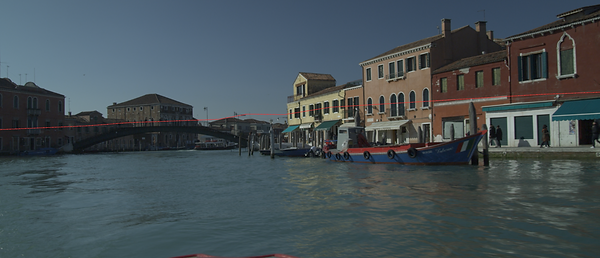
Next, I added a camera tracking node. First I changed the mask to "Source Alpha". Then I click track and then solve. This tracked the camera moving through the scene. However, it had a lot of red and orange X's. To fix this I went into the AutoTracks tab. I clicked Delete unsolved and Delete Rejected. I

then went back into the camera tracker tab and click Update Solve. I then repeated this process all of the red and orange X's were gone.
Then, I went to frame 1025 and added a FrameHold. I then added a RotoPaint node before it and painted out the windows. I then connected the FrameHold to a copy node and connected that to a roto node and Roto'd around the windows. Then I connected the copy node to a Premult node.

After that, I copied the FrameHold and connected it to the camera. I then connected the FrameHold to a Project3D node and put that under the Premult node. Then I added a card and went into 3D view. I lined the card up with the point cloud.

Next, I added a ScanlineRender node. I connected the cam pipe to the camera. I connected the obj/scn to the card. I copied the undistorted reformat node and connected it to the bg pipe.

Finally, I connected the ScanlineRender to the re-distorted STMap. Then I connected the re-distorted Reformat node to the A pipe of a merge node and connected the B pipe to the original image.
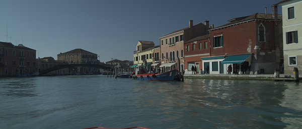
Final Video

3DEqualizer Tracking
First, I imported the footage.
I then had to cache the footage. I did this by clicking on "Playback/ Export Buffer Compression File...".
Next, I set up my camera settings. I did this by clicking on the yellow text under "Cameras". I then changed it to lens. I then put in the details of the camera in. I was provided with them.
Then, I move to a frame that was not blurry. I pressed "ctrl" and clicked on the part that I wanted to track. Then I pressed "G" and then "Track". If the track stoped then I had to adjust the size of the box and press "G" and then "Track" again.


I repeated this process multiple times to track multiple points.
Next, I wanted to get a better track so I went in to the lens settings and clicked the adjust box next to "Distortion" and "Quartic Distortion". I also changed the focal length from "Fixed" to "Adjust". I then clicked "Windows/Parameter Adjustment Window". I clicked the button that said "Adaptive All" and then clicked "Adjust".

Then, I clicked "Calc/Calc All From Scratch". This converted the 2D points to 3D and created a camera from them points.
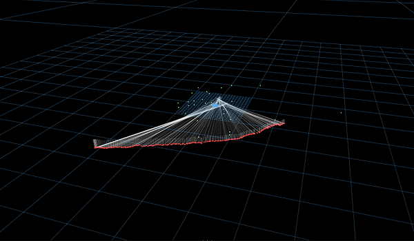
Next, I selected three points on the ground and then clicked "Edit/Align 3 Points To/ XZ Plane". I also selected one point on the ground and clicked "Edit/Move 1 Point To/Origin".

Then, I set selected two points and set the distance between the to scale it up. I click "Constraints/Create Distance Constraint..".

Finally, I added a locator to all of the points by clicking on the points and then clicking "Geo/Create/Locators". I also created a cylinder and then exported everything for nuke.

Importing Tracking Data Into Nuke
First, I imported the footage and all of the things that were exported from 3D Equalizer.
Then, I added a Scene node and connected that to a ScanlineRender node. I connected the camera to the scanlineRender. I also connected the cylinder and the locators to the scene.

I added a wireframe node to the cylinder and a constant to the locator node. I made the constant blue.

However, it did not aline properly with the footage. To fix this I added a Reformat node to the bg pipe of the ScanlineRender node. I set the type to scale and set it to 1.1. I then changed the resize type to none. I then added another Reformat after the ScanlineRender node and change the resize type to none.

Finally, I needed to add lens distortion. I imported the lens distortion node which I exported from 3D equaliser and put it under the Reformat node. I then change the direction to distort. I also merged it with the original footage.

Final Video

Clean-up using tracking data
First, I imported the footage and all of the things that were exported from 3D Equalizer.
Next, I had to undistorted the footage. I did this by adding a BlackOutside node. Then I added the distortion node from 3D Equaliser. I also added a reformat node and set the type to scale and set it to 1.1.

After that, I added a FrameHold node and set it to frame 1119. I then put a RotoPaint node before it and paint out the writing on the sign.

Then, I added a copy node and connected the B pipe to the FrameHold node, and connected the A pipe to a roto node. I roto'd around the sign and used a blur node to feather the edges. I then added a premult node.

Next, I added a Scene node and connected that to a ScanlineRender node. I connected the camera to the scanlineRender. I also connected the locators to the scene.

After that, I added a card and connected it to the scene node and line it up with the locators in the 3D view. I then connected a Project3D node to the premult and then connected that to the card. I copied the FrameHold and connected it to the Cam pipe of the Project 3D node. I also connected the camera to the Framehold.

Then, I had to re-distort it. I copied the reformat nod from before and added it to the bg pipe of the ScanlineRender node. I then added another reformat node and put it under the Scanline render node. I changed the resize type to "none". Then I added the distortion node from 3D equaliser and changed the direction to "distort".

Finally, I merged it with the original footage.

Final Video

Distortion using a grid
First, I 3D tracked a scene in 3D equaliser. I also made sure that the distortion on the camera was set to "3DE4 Radial - Standard, Degree 4".

Next, I right clicked on the camera and clicked "Add New/Reference Camera". I then clicked on the camera and imported the image of the grid that was provided.

Then, I went into the Distortion Grid Controls view. It had a grid in the middle. I aligned the points with two of the squares on the grid and then clicked "Snap". This aligned all of the points.

After that, I clicked "Edit/Add Points" and added enough to cover the whole grid.

Finally, I clicked "Calc/Calc Distortion/Camera Geometry...". Then I clicked "Calc Lens Parameters" and then "Set Parameters". This added the distortion to the 3D track that I did.

3D Tracking Assignment
For this exercise I had to 3D track a scene using 3D equaliser. Then, imported it into nuke and remove the fire exit sign. I also had to create a cube cube and comp it into to the shot. Finally, I had to show the tracking point using locators. First, I imported the video.
Next, I set up my camera settings. I did this by clicking on the lens. I then put in the details of the camera in, which I was provided with them.

Then, I added all of the tracking markers. I did this by pressing "ctrl" and clicking on the part that I wanted to track. Then I pressed "G" and then "Track". If the track stoped then I had to adjust the size of the box and press "G" and then "Track" again. I did this 40 times and made sure that I tracked thing that were close and far away from the camera. Then, Pressed "Alt C" to solve the points into 3D space.
After that, I wanted to get a better track so I went in to the lens settings and clicked the adjust box next to "Distortion" and "Quartic Distortion". I also changed the focal length from "Fixed" to "Adjust". I also wanted make the the lens more accurate, so I set the focal length to "Adjust". I then clicked "Windows/Parameter Adjustment Window". I clicked the button that
said "Adaptive All" and then clicked "Adjust". This calculated the distortion and focal length of the lens.
Next, I selected three points on the ground and then clicked "Edit/Align 3 Points To/ XZ Plane". I also selected one point on the ground and clicked "Edit/Move 1 Point To/Origin".
Then, I selected two points on the edge of the table. I click "Constraints/Create Distance Constraint". I new the size of this because it was provide with survey data.
After that, I created a cube and then selected one of the point and clicked "3D Models/Snap To Point". I also added a locator to all of the points by clicking on the points and then clicking "Geo/Create/Locators".

Then, I exported everything into nuke.
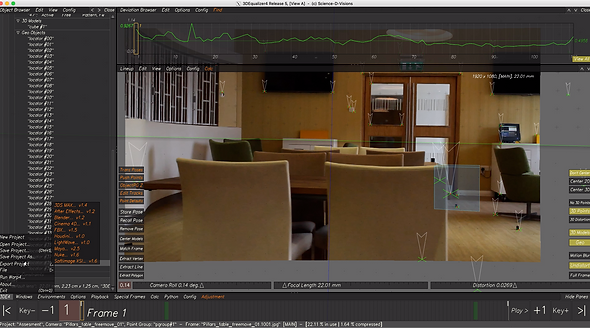

Next, I imported the footage and all of the things that were exported from 3D Equalizer.

Then, I added a Scene node and connected that to a ScanlineRender node. I connected the camera to the scanlineRender. I also connected the cube and the locators to the scene. I then merged the scan line render with the original footage.
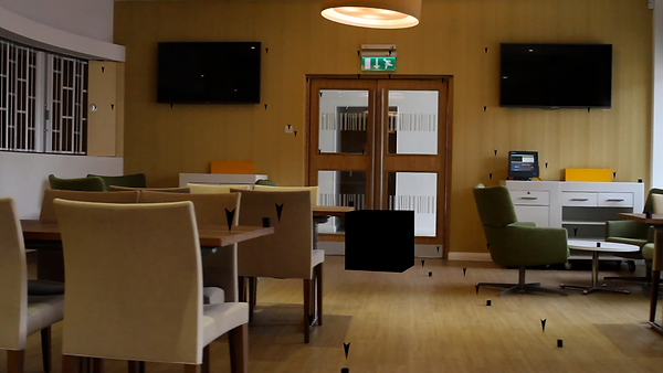
Next, I duplicated the cube and added a constant to one of them and a wireframe node to the other. I changed the constant so the alpha was set to 0.5. I also added a constant to the locator node and I made the constant blue.

However, it did not aline properly with the footage. To fix this I added a Reformat node to the bg pipe of the ScanlineRender node. I set the type to scale and set it to 1.1. I then changed the resize type to none. I then added another Reformat after the ScanlineRender node and change the resize type to none.

Then, I needed to add lens distortion. I imported the lens distortion node which I exported from 3D equaliser and put it under the Reformat node. I then change the direction to distort. I also merged it with the original footage.

Next,I created another tree. I added a FrameHold node and set it to frame 1001. I then put a RotoPaint node before it and paint out the writing on the sign.

Then, I added a copy node and connected the B pipe to the FrameHold node, and connected the A pipe to a roto node. I roto'd around the sign and used a blur node to feather the edges. I then added a premult node.

Next, I added a Scene node and connected that to a ScanlineRender node. I connected the camera to the scanlineRender. I also connected the locators to the scene.

After that, I added a card and connected it to the scene node and line it up with the locators in the 3D view. I then connected a Project3D node to the premult and then connected that to the card. I copied the FrameHold and connected it to the Cam pipe of the Project 3D node. I also connected the camera to the Framehold.

Then, deleted the locators and merged the ScanlineRender node with the original footage.

Next, I added a grade node between the ScanlineRender node and the merge node and animated it to match the colours.

Finally, I merged the first tree with the second tree.

Final Video

Assignment 2
For this assignment I was provided with a Maya file which included and an animated camera that was created in 3D equalizer. It also included the video as a background, a plane with an aiShadowmat material applied to it, a sphere and a light. I had to delete the sphere and replace it with something else. I also had to match the lighting of the scene.

First, I made the sphere chrome. This made it go black because there was nothing for it to reflect.

To fix this I had to recreate the scene using the tracking markers. I also had to recreate the lighting. I didn't need to do it in a lot of detail because it will only be visible in the reflections and lighting.

To make it only appear in the reflections and lighting I selected each of the objects and went into the attribute editor and went into the Arnold tab. I turned off "Primary Visibility" and "Cast Shadows".

I then did a test render. I made the sphere a blue plastic and rendered out the sequence. I also did an ambient occlusion pass. I imported it them into after effects and set the blending mode on the ambient occlusion pass to multiply and changed the opacity to 50%. Then I added an adjustment layer and added an "Optics Compensation" and "Transform" effects to fix the lens distortion.
1st Render - Robot
First, I exported a robot from another project that I had rigged and applied motion capture to and imported it into the 3D tracked scene. Then, I deleted the ball and moved the robot to the correct position. I also had to scale up the scene to match the size of the robot.

I then used the time editor to change which part of the animation that I wanted to use.

Next, I adjusted the Arnold Render settings to make the final render look more realistic.
Finally, I rendered it. I also did an ambient occlusion pass. I imported it them into after effects and set the blending mode on the ambient occlusion pass to multiply and changed the opacity to 50%. Then I added an adjustment layer and added an "Optics Compensation" and "Transform" effects to fix the lens distortion.
1st Render - Robot (Second Draft)
The first problem was the robot's feet were not touching the ground. To fix this I just had to move the robot down slightly.

The second problem was the robot was too dark. I fixed this by increasing the brightness of the lights.
The third problem was there was not a reflection of the robot on the TV. To fix this I first deleted the background video so I had the robot with a transparent background. I could get the background back by putting it as the layer behind the robot in after effects.

Next, I made all of the geometry hidden and turned off primary visibility for the robot. I then added a plane and lined it up with the TV and added an aishadowmat material to it and turned on specular. I originally set the IOR to 1.5 because it is glass. However, the reflection was to faint to see. I rendered 3 different passes and with different IOR values and put
them as a layer between the main render and the background in after effects. I decided to use an IOR of 3.5.
Final Render
Breakdown
2nd Render - Heads on Pillars
First, I got the Viking head that I made for the Digital sculpting module and added it to a new scene.

Next, I 3D modelled a pillar to put the head onto.

I then imported them into substance painter and created three different versions. One made out of marble. The other out of stone, and the third out of sandstone.
Here are the finished, textured versions. I also uploaded them to sketchfab.


I then imported them into the 3D tracked scene and applied the textures.


Next, I adjusted the Arnold Render settings to make the final render look more realistic.
I deleted the background video so I had the pillars with a transparent background. I could get the background back by putting it as the layer behind the pillars in after effects.

Next, I made all of the geometry hidden and turned off primary visibility for the pillars. I then added a plane and lined it up with the TV and added an aishadowmat material to it and turned on specular. I set the IOR to 3.5.

Finally, I rendered it. I also did an ambient occlusion pass. I imported it them into after effects and set the blending mode on the ambient occlusion pass to multiply and changed the opacity to 50%. Then I added an adjustment layer and added an "Optics Compensation" and "Transform" effects to fix the lens distortion.
Breakdown
3rd Render - Grizzly Bear
First, I used ZBrush to sculpt the shape of the bear. The main brushes I used were the standard brush, the move brush, the smooth brush, the trim dynamic brush and the dam standard brush. I used the standard brush to and remove material from the mesh. I used the move brush to move the mesh into the correct shape. I used the trim dynamic brush to create flat planes I used the dam standard brush to
create small and sharp details. Finally, I used the smooth brush to smooth out parts of the mesh.
Next, I changed the shape of the bear by focusing more on the anatomy.
I then, changed the shape of the back legs because it did not look correct where the thigh joined the stomach. I also made the feet bigger. I realised the bear walks on it toes on its front feet but not his back.
After that, I change the shape to emphasise the muscles. This made it look a lot more realistic because I had to completely change the lower part of the legs.
The final change to the bears shape that I made was I reduced the size of the muscles because they looked too defined.
This is a timelapse of me making the bear.
Next, I imported the bear into Maya. I applied an AiStandardSurface to the different parts. I also had to do a planar UV map to the eyes to I could add an eye texture easily.
Then, I textured it using Substance Painter. I started with a skin smart material and then painted on different layers for the different parts of the bear.
Next, I exported the materials from substance painter and applied them to the model in Maya. I made the skin and a Subsurface Scattering material. I also made the claws a Refractive material.
I then rigged it. I added joints along the spine and legs. I then mirrored the joints on the legs and then connected all of them to the spine. I also rigged the head. I added joints of the jaw and tongue and connected them to the main head joint.
After that, I skinned the bear. This was difficult because the legs are connected to the body so the skin has to move a lot more than a humans would.
Then, I added controls. I created the foot controls by adding an IK solver from the hip to the ankle. I then created another IK solver for the toes. then I added a controller to the for the toes and the ankle. I parented the toes controller under the ankle so I could rotate the toes. For the hands, I did the same. However, I made the wrist and fingers separate controllers and created another controller that
contains both of them. I then added an aim constraint to the toes so they point down when you lift the foot up. Then, I added controllers for the body, neck and head. I also added an aim constraint for the eyes.
Next, I create blend shapes to control the face. I made it so I could close each eye and lift up its top lip to show its teeth. I also made it so when it closes its mouth, the mouth will change shape to make sure the teeth are not going through it.
Then, I used Xgen to add fur to the bear. I created density maps using substance painter because I had already created masks for the skin. I also used substance painter to create a noise map and a colour map the controls the melanin value for the AiStandardHair material.

I then imported it into the 3D tracked scene and created an animation.

Next, I adjusted the Arnold Render settings to make the final render look more realistic.
I deleted the background video so I had the bear with a transparent background. I could get the background back by putting it as the layer behind the bear in after effects.

Finally, I rendered it. I also did an ambient occlusion pass. I imported it them into after effects and set the blending mode on the ambient occlusion pass to multiply and changed the opacity to 50%. Then I added an adjustment layer and added an "Optics Compensation" and "Transform" effects to fix the lens distortion.
Breakdown