Wiggling Tentacle
First, I 3D modelled a tentacle. I made sure that I set the subdivision height to 9.

Next, I added a skeleton to it. I did this by switching over to the rigging tab and then I clicked on the create joints tool. I made sure that I added a joint every 3 subdivisions.

This allowed me to move and rotate the different parts of the tentacle by clicking on the joints. However, I wanted to make it easier to control. To do this I added three nurb circles and moved them so they lined up with the joints. For the bottom one, I made all of the joints a child of it. For the other two, I had to click on one of the circles and then click on the joint. I

then added an orient constraint. I then made the top two joints a child of the bottom one and made the top one a child of the middle one.
After that, I wanted to animate the tentacle. I did this by adding an expression to the top two circles. This made them rotate randomly.

Next, I created a MASH network. I added a sphere and then changed the distribution type to mesh. I then added the sphere as the mesh. I set the number of points to 25 and I changed the method to Random Vertex.
Finally, I added another Mash network. I set the distribution type to spherical and the number of points to 10. I also added a signal node and a random node to make them move around in random directions.
Arnold Render

Robot Rig
I was provided with a character made out of spheres and cylinders. I had to rig the character so I could control it.

I started with the arm. First, I created 4 joints while holding down "X". This alined them all in the X-axis.

Next, I lined all of the joints up with the correct parts on the robot. To do this I clicked on all of the spheres and then clicked on "Display/Transform Display/Local Rotation Axes". This allowed me to see the centre of each sphere. I then snapped the shoulder joint to the correct part. To do the elbow I rotated the shoulder so the joint was aligned properly and the

snapped the joint in the X-axis. I did the same for the wrist. I also deleted the fourth joint because I didn't need it anymore.
Then, I clicked on each joint and went into the attribute editor. I had to copy the rotation from the transform attributes into the joint attributes. Then, I set the rotation in the transform attributes to 0.

I used the same process to do all of the other joints.

Finally, I parented all of them together.

Arm Rig
I was provided with a 3D model of an arm with some joints. The joints were animated for a technical animation. I had to correctly connected the arm to the joints.
First, I clicked on the joints and then clicked on the arm. Then I clicked "Skin/Bind Skin". This worked. However, the arm was not bending correctly.
To fix this I used the "Paint Skin Weights" tool. The lighter the colour, the more the joint will control it.
Claw Rig
I was provided with a 3D model of a robot with the joints. For this exercise, I had to create a control to open and close the hands and also spin them around.

First I created a nurb circle and snapped it to the wrist joint. I called "CLAW_CNTRL". Then I click freeze transformations.

I then clicked on the circle and clicked "Key/Set Driven Key/Set" to open the dialogue box. I then added an attribute to the circle called "CLAW_OPEN". I set the minimum to 0 and the maximum to 1. This created a slider in the attribute editor. I then clicked load driver. Then I clicked on the claws and clicked load driven. Next, I clicked on all of the rotations and clicked
key. Then I moved to a different frame and changed the slider to 1. I then opened all of the claws and clicked key again. I could now control them using the slider.
Next, I added another attribute called WRIST_SPIN. I then right-clicked on the attribute and click create new expression and added a script to it which was provided.

FK vs IK
I was provided with a 3D model of a robot with the joints. For this exercise, I had to create an FK rig for the right arm, and an IK rig for the left arm.
FK
First, I created three nurb circles and aligned them with the right shoulder, elbow and wrist. Then I clicked freeze transformations on all of the circles. I then clicked on the first circle and then clicked on the shoulder joint. I click on "Constrain/Orient". This made the shoulder joint rotate with the circle. I did this for the elbow and wrist and then parented the circles under each other.
IK
First, I created a nurb circle and aligned it with the wrist. I created another and put it behind the elbow. Then I clicked freeze transformations on them. I then used the "create IK handle" tool and clicked on the shoulder joint and then the wrist joint. This worked but it bent int the wrong direction. to fix this I went into the IK solver attributes and change the third
pole vector to a minus. Then I click on the circle on the wrist and the ikHandle and clicked "Constrain/Parent". Finally, I clicked the circle behind the elbow and the ikHandle and clicked "Constrain/Pole Vector".
Back Controls
First, I created a nurb circle and aligned it with the root joint. I made it bigger and then clicked "Modify/Freeze Transformations". Then I clicked on the circle and then the root joint and clicked "Constrain/Parent".

Then, I created two attributes. FOR BACK CURL and L R CURL.

Next, I selected the three different spine joints and clicked "Key/Set Driven Key/Set". Then, I clicked on the circle and clicked "load driver". For the driver, I selected "FOR BACK CURL" and for the driven, I selected all of the joints and then selected "Rotate Y" and clicked key. Then, I set "FOR BACK CURL" to 4 and rotated all of the joints forward by 45 degrees and clicked key again. I
then set "FOR BACK CURL" to -4 and rotated all of the joints backwards by 45 degrees and clicked key again. This made it so I could control rotate the back forward and backwards using the circle control. I did the same for the "L R CURL".
After that, I created another nurb circle and aligned it with the root joint. I made it bigger and then clicked "Modify/Freeze Transformations". I then opened the connection editor and loaded both of the circles. I clicked on "Translate Z" on the 2nd circle and then clicked on the "FOR BACK CURL". I then clicked on the "Translate X" and clicked on the "L R CURL".
Finally, I wanted to create another control for the spine. First, I created another nurb circle and aligned it with the joint. Then I clicked "Modify/Freeze Transformations". I then opened the node editor and added the joint and the nurb circle to it. The joint rotated in the opposite way to the circle. to fix this I added a "multiplyDivide" node and connected it to "rotateX". I changed
the X value on input 2 from 1 to -1. I added a "floatMath" node and connected the "floatB" to "outputX". I then connected the "joint Y rotation" output to "floatA". Finally, I connected the "floatMath" output to the "Rotate Y" value on the joint.
Rigging springs and hydraulics
I was provided with a model of a robots arm that had an IK rig applied to it. I also had a hydraulic and spring next to it.

First, I parented the dark blue part to the shoulder joint and the light blue side to the wrist joint. I then clicked on the dark blue sphere and then the light blue sphere and added an aim constraint. I then did the same again but clicked on the light blue sphere first. This made it so they were both looking at each other.
Now I had to rig the spring. First, I went into edge selection mode and double-clicked one of the edges. Then, I clicked "Modify/Convert/Polygon Edges to Curve." Then, I clicked "Deform/Wire". I selected the spring and pressed enter and selected the curve and pressed enter. I then had to change the drop off distance to a high number. I also selected the curve and clicked "Edit/Delete by Type/History".
Next, I used the CV curve tool to create a line going through the middle of it with one point in the middle and one each end. I then added another wire deformer so the line controlled the curve for the spring.
After that, I added a locator and moved it to the end of the dark blue cylinder. I then parented the locator to the cylinder.

Then, I selected one of the points on the line and clicked "Deform/Cluster". I did the same for all three of them. This made it so I could control the points without going into edit mode.
Finally, added a point constraint between one of the clusters and the locator and another cluster and the light blue sphere. I then selected the two clusters on the end and then the one in the middle and added a parent constraint.
Crumbling Cube Man
I was provided with a character that had been animated using motion capture.
First, I added a cube and changed the scale to 0.2. then I added a MASH network to it and changed the distribution to "Mesh". I then added the character into the "Input Mesh" slot. I then increased the number of points and turned on "Use Face Area".
There was a problem where the cubes would move around as the character moved. To fix this I moved the timeline to frame -20. I then created a keyframe with all of the joints at 0 so it was a T-Pose. I then created a mesh from MASH points. Then, I skinned the points and the mesh to the joints.
I then changed the input mesh to the mesh from points and changed the method to vertex.
I then added a color node and set the colour to red. Then I set the random hue to 1. This made every colour random.
Next, I added a dynamics node. This made the cubes fall. to make them land on the floor I change the bullet solver position to 0. I also added a plane for the gound.
Then, I added a falloff object to the position strength. I inverted it and changed the shape to a cube and the mode to add. Then I rotated a scaled it so it was an angle and the man walked into it.
When I rendered it the colours did not display. To fix this I hade to make sure that Color Per Vertex was turned on in the MASH settings and Export Vertex Colors was turned on in the mesh settings. I then added an AiStandardSurface material to the cubes and added an "AiUserDataColor" node and typed in "colorSet".
Finally, I set up the camera position. I also added an AiShadowMat to the floor and made it shiny. I added a HDRI for the lighting.
Final Render
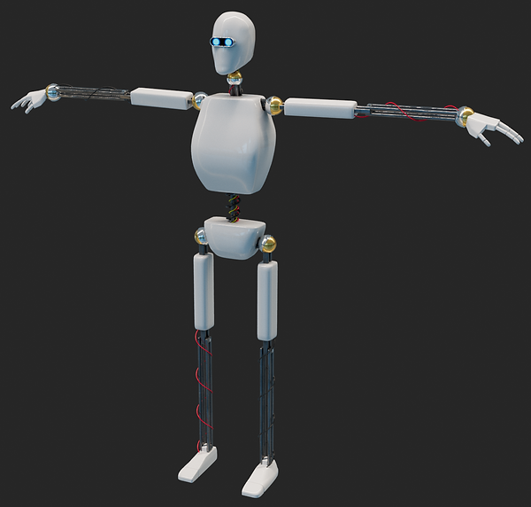
Robot Rig
First, I 3D modelled a Robot and textured it using substance painter.
I started with the arm. First, I created 4 joints while holding down "X". This alined them all in the X-axis. Next, I aligned the first joint with the centre of the shoulder. To do this I selected the joint and then the sphere and clicked "Modify/Match Transformations/Match Translations".To do the elbow I rotated the shoulder so the joint was aligned properly and then

moved the joint in the X-axis. I did the same for the wrist. I also deleted the fourth joint because I didn't need it anymore. Then, I selected each joint and went into the attribute editor. I had to copy the rotation from the transform attributes into the joint attributes. Then, I set the rotation in the transform attributes to 0.
I used the same process to do the left leg and the spine.

After that, I rigged the hand. To rig the fingers I used the same process as before. I then had to select the first joint of each of the fingers and then the wrist joint. I then clicked "Skeleton/Connect Joints" and changed it to "Parent Joint". This created a joint connecting the fingers to the wrist.

Then, I mirrored the arm and the leg to the other side. I did this by clicking "Skeleton/Mirror Joints". I changed it to mirror across YZ. I also put "L" in the "Search for" and "R" in the "Replace with". This changed all of the names from left to right.

Next, I connected all of the joint together by selecting two joints and then clicking "Skeleton/Connect Joints" and changing it to "Parent Joint".

After that, I parented all of the parts to the different joints.

I had a problem where the body would not move correctly with the spine. To fix this I had to select the joints and then the body an then click "Skin/Bind Skin".
I also had to do the same for the wires.
Next, I added hydraulics with springs. I used the same method to make them as I did previously.
After that, I added IK handles to the arms and legs. First, I created a nurb circle and aligned it with the wrist. I created another and put it behind the elbow. Then I clicked freeze transformations on them. I then used the "create IK handle" tool. I clicked on the shoulder joint and then the wrist joint. Then I parented the circle to the ikHandle. I selected the circle
behind the elbow and then the ikHandle and clicked "Constrain/Pole Vector". This made it so I could control the rotation of the arm. I also did this for the other arm and the legs.
Then, I added some controls for the wrists and ankles. I added a nurb circle and aligned it with the wrist. I then made the circle a child of the elbow joint and a parent of the wrist joint.
Next, I added some controls for the hips, spine and neck. I did this the same way I did the wrists and ankles. I also did the toes.
After that, I added a control for the head. I did this by creating a nurb circle and then moving it in front of the head. I then added an aim constraint between them.
Finally, I created a control to open and close the fingers. I selected the wrist control and added an attribute. Next, I selected all of the joints for the hand and clicked "Key/Set Driven Key/Set". Then, I clicked on the circle and clicked "load driver". For the driver, I selected the attribute I created, and for the driven, I selected all of the joints and then selected all of the
rotation parameters and clicked key. Then, I set the attribute I created to 1 and rotated all of the joints so the hand was shut and clicked key again. The thumb was moving to fast and went through the fingers. To fix this I set the attribute to 0.5 and then move the thumb so it wasn't in the way of the fingers. I also did the same for the other hand.
Finished Rig
Spline IK
I was provided with a model of a cat that had the joints of the spine skinned to it.

Next, I clicked "Skelton/Create IK Spline Handle". I set the number of spans to 3. I then clicked on the one second from one end and then the second from the other end. This created a curve and an IK handle.

After that, I selected the curve and clicked "Component Display/ Disp CV". This allowed me to control the cat by clicking on the CV points.
Then, I selected the two at the end and clicked "Deform/ Create Cluster". I did the same for both ends and then added a cluster for each point in the middle.
Next, I added a Nurb circle and changed the scale to 10. I then grouped it and parented the group to the joint. I then set all of the attributes to 0. I then unparented it. Then I rotated the circle 90 degrees. Next, I went into edit mode and moved the circle down and changed the scale. After that, I added a point constraint between the circle and the cluster. I did the same for the other 4 clusters.
After that, I parented all of the controls together. I put the "Spine_Control_Offset_02" under the "Spine_Control_01" I did this until all of them were parented together. I could select all of the circles and rotate them all together.
Then, I added some joints to the tail. I did this by clicking "Skeleton/Add Joints". I parented the top of the tail joint to the end of the spine joint. Then I selected all of the joints in the tail and then the mesh and clicked "Skin/Edit Influences/Add Influences"
Mesh Influences
I was provided with a model of an arm that had the joints skinned to it.

First, I created a sphere and parented it to the shoulder joint. I then move and scaled it to create the shape of the bicep.

Next, I selected the sphere and then the mesh and clicked "Skin/Edit Influences/Add Influences". I then went into the "Paint Skin Weights" tool and painted where I wanted it to affect it.
Finally, I selected the sphere and clicked "Key/Set Driven Key/Set". Then, I clicked on the elbow joint and clicked "Set Driver". I selected "Rotate Y" for the elbow and all of the scales for the sphere and the clicked set. Then, I rotated the elbow 90 degrees and then scaled the sphere to the shape I wanted and clicked key again.
Mouth blend shape
I was provided with a model of a mouth which was skinned so I could control the top and bottom lips. I had to rig it using blend shapes.

First, I changed the workspace to "pose sculpting". Then I went into the shape editor tab and selected the mesh. I then clicked "Create Blend Shape". Then I right-clicked on the blend shape and clicked "Add Target". I then edited the mesh so the left side of the mouth was smiling and then turned off edit mode. I could now control the mouth using a slider.
Next, I right-clicked on the target and clicked "Duplicate". I then right-clicked on the new target and clicked "Flip Target". I could now control both sides.
After that, I selected both of the targets and clicked "Add Combination Target". I then used the sculpting tools to change the shape of the mouth to make it stretch when it smiles.
Mouth Pose Editor
I was provided with a model of a mouth which was skinned so I could control the top and bottom lips. I had to rig it using blend shapes.
First, I changed the workspace to "pose sculpting". Then I went into the pose editor tab. I selected the joints that control the bottom lip and clicked "Create Pose Interpolator". I then clicked "Add Pose". I rotated the joints to 10 degrees and then clicked "Update Pose". I then sculpted the mouth in the shape that I wanted to make it look more natural. Now when I rotate the joints it creates a more natural look.
Mouth Control Rig
I was provided with a model of a mouth which was skinned so I could control the top and bottom lips. I had to rig it using blend shapes.
First, I created two nurb circles and moved them in front of the mouth. I rotated and changed the scale of them and then clicked "Freeze Transformation".

Next, I created an IK handle. However, I changed the solver from "Rotate-Plane Solver" to "Single_Chain Solver". I created one for the top part of the joint and one for the bottom part of the joint.
I then parented the main joint to the big circle and the second joint to the smaller circle. Then, I parented the small circle to the big circle.
Next, I changed the workspace to "pose sculpting". Then I went into the pose editor tab. I selected the joints that control the bottom lip and clicked "Create Pose Interpolator". I also went into the shape editor and added a blend shape.

After that, I clicked "View/Advanced" in the Pose Editor. I also opened the outliner clicked "Display/Attributes(Channels)". I then went into the driver settings and clicked edit and added the translate values from the controllers.
Finally, I moved the circles down and then clicked add pose. I then used the sculpting tools to make the mouth look more natural.
Eyelid Rig
I was provided with a model of an eye an eyelid. I had to rig it using blend shapes.
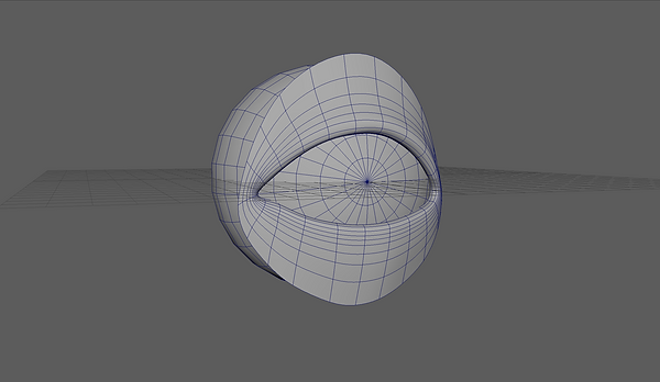
First, I changed the workspace to "pose sculpting". Then I went into the shape editor tab and selected the mesh. I then created two blend shapes "Base_Mesh_01" and "Eye_Blink_01". Then I right-clicked on the second blend shape and clicked "Add Target". I then edited the mesh so the eyelids were closed. I could now control the eyelids using a slider.
However, both the eyelids are moving at the same speed. to fix this I changes the slider to 0.650. Then I right-clicked on the target and clicked "Add In-between Target". I then used the erase target tool to make the bottom eyelid go back to its original position. This made the top eyelid move at a constant speed, but the bottom eyelid won't move until the eye was almost shut.
Sub Pivot Controls
I was provided with a model of a cat that has joints applied and has been skinned. There was also a control on the foot, but it didn't work.

First, I clicked "Skeleton/Create IK Handle". Then, I selected the shoulder joint and then the wrist joint.
I then parented the IK handle under the "PAW_CNTRL"./
Next, I added another IK handle between the wrist and the base of the hand. This made it so I could bend the hand.
After that, I added another IK handle between the base of the hand and the ender of the finger.
Then, I parented all of the IK Handles under the "PAW_CNTRL".
Next, I selected the toe IK Handle and pressed "CTRL G" on the keyboard. This created a group. I then changed the pivot point of the group to the base of the hand.
I then grouped the other two IK Handles and moved the pivot point to the base of the foot. When I rotated it the arm would flex.
After that, I grouped both of the groups and moved the pivot point to the base of the foot. When I rotated it the arm would twist.
Then, I created another group and change the pivot to the end of the toe. Then I grouped that and change the pivot to the ankle.
Next, I created custom attributes for the "PAW_CNTRL" ant then liked them to the groups using the connection editor.
Next, I created custom attributes for the "PAW_CNTRL" and then liked them to the groups using the connection editor.
Finally, I added a nurb circle and put it behind the elbow joint. Then I clicked "Freeze Transformations" and added a pole vector constrain between the nurb circle and the IK handle.
Squash and Stretch
First, I created 4 spheres which were different colours and added a joint chain to them.
Then, I created a spline IK for the spheres. Next, I duplicated it and deleted everything expert the top and bottom joints. I then skinned the curve to the joints.
After that, I created two nurb circles and patented the joints under them. I could then move the top and bottom of the spheres. However, I could not control the height.
I then went into the node editor and added a "curveInfo" node. I connected the "World Space [0]" to the arc length. This told me how long the curve is.
Next, I added a multiply and divide node and connected the arc length to input 1x. I then set Input 2x to the same number and set it to divide. Then, I connected Output X to the scale X of all of my joints.
Finally, I created another MultiplyDivide node and connected Output X to Input 1X. I change the operation to power and input 2x to 0.5. I then created another multiply divide node and connected output X to input 2X. I change the operation to divide and set input 1x to 1. I then connected output X to Scale Y and Scale Z of the joints.
Arm Squash and Stretch
I was provided with an arm that had been skinned.

First, I created an IK handle with a controller for it. Then, I used the "Distance tool" to see the distance between the controller and the shoulder.
I then created an attribute and added an expression to it. The expression did the same thing as I did previously with the balls. However, it only stretches and doesn't squash.
Finally, I opened the node editor and connected the Out Scale value to the Scale X of the joints.
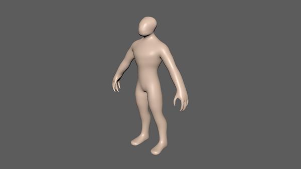
Arm Squash and Stretch
I was provided with a character. I had to apply motion capture data to it and then use X-Gen to add fur to it.
Next, I went into the human IK window and created a quick rig. This allowed me to get a simple rig very quickly. I also added the rig to the human IK system so I could apply motion capture to it.
Then, I imported some motion capture data into Maya. I had to use the human IK system to create a character definition. then I could go back to the quick rig and change the source to the mocap data.
After that, I made all of the joints hidden. I then switched the layout to "Xgen - Interactive Groom". Then, I added interactive hair to the alien.
Next, I changed the taper settings to make each hair go to a point. I also changed the density to get more hairs.
Then, I painted a density mask. I wanted to make the head, hands and feet have no fur on them.
Next, I imported the density mask into photoshop and removed all of the parts that I missed.
Then, I added a guides modifier and then added a sculpting layer to that. I then combed the hair to the correct shape.
After that, I added a clump modifier. However, the clumps did not align with the guides. To fix this I opened the node editor and connected the "Out Spline Data" to the "Input Points" I then added another clump modifier and made it smaller to add detail. Next, I added a noise modifier to add randomness.
I then cashed the animation of the fur to make it run quicker.
Finally, I change the material of the hair to an aistandardhair and made it blue. I also change the character to a skin material. I added a floor and a hdri.
Bifrost
First, I opened the content browser and added a pre-made character.

Next, I subdivided the mesh. Then, I added an AiSkydomb and change the samples to 3. Then, I clicked "Arnold/Utilities/Render Selection to Texture". This created a texture with the for the character that was more detailed than the diffuse.
After that, I added some motion capture data to the rig that I got from the content browser. I applied it using HumanIK.
Then, I selected the mesh and clicked "Cashe/Alembic Cashe/ Export Selection to Alembic Cashe". I made sure that I turned on "UV Write" and "Write Color Sets". I then deleted the original character. and imported the new cache one.
Next, I opened the Bifrost graph editor. Then, I added the character to it. I also added 4 nodes. "simulate_mpm", "source_mpm_snow", "mpm_solver_settings" and "collider". I then connected them to the correct inputs and outputs.
I then connected the character to the "source_mpm_snow". I also added a plane and connected that to the "collider". I added the "simulate_mpm" to the output.
There was a problem where it only simulated the top half of the character. To fix this I had to change the resolution mode of the collider from "Relative" to "Absolute". I also change the detail size to 0.15.
Next, I applied the texture to the vertex. I did this by changing the material to a lambert. Then, I went into the vertex paint settings and made the mesh white. Then, I imported the texture.
After that, I applied the colour of the character to Bifrost. I did this by adding a "Set_Property" node and connecting it to the "source_mpm_snow". I then applied the colorSet from the character to the Bifrost.
I then changed the start and end from to frame 30 so it only simulates after the jump. I also changed the direction so it doesn't spread out as much.
Next, I adjusted the "source_mpm_snow" settings. I set the cohesion to 2 to make it keep its shape more. I also changed the "Initial Firmness" to 700 to make it harder to break. Another thing that I changed was the particle settings. I set the "Particles Per Voxel" to 24 and the "Particle Display Scale" to 0.5. This created smaller particles which created more detail.

I also changed the collider settings. I set the "Bounciness" to 0.05 to make the particles bounce around less. I also set the "Friction" to 0.9 to stop them from sliding.

Next, I cashed the file using the "File Cashe" node.
After that, I started to set up the lighting. However, the particles appeared white. To fix this I had to create a new AiStandardSurface material and apply it to the particles.
Finally, I set up the lighting. I added a AiShadowMat material to the floor and added an AiSkyDomb for the background this made an infinite background. I used a HDRI for the Lighting.
Final Render
Bear Rig
First, I used ZBrush to sculpt the shape of the bear. The main brushes I used were the standard brush, the move brush, the smooth brush, the trim dynamic brush and the dam standard brush. I used the standard brush to and remove material from the mesh. I used the move brush to move the mesh into the correct shape. I used the trim dynamic brush to create flat planes I used the dam standard brush to
create small and sharp details. Finally, I used the smooth brush to smooth out parts of the mesh.
Next, I changed the shape of the bear by focusing more on the anatomy.
I then, changed the shape of the back legs because it did not look correct where the thigh joined the stomach. I also made the feet bigger. I realised the bear walks on it toes on its front feet but not his back.
After that, I change the shape to emphasise the muscles. This made it look a lot more realistic because I had to completely change the lower part of the legs.
The final change to the bears shape that I made was I reduced the size of the muscles because they looked too defined.
This is a timelapse of me making the bear.
Next, I imported the bear into Maya. I applied an AiStandardSurface to the different parts. I also had to do a planar UV map to the eyes to I could add an eye texture easily.
Then, I textured it using Substance Painter. I started with a skin smart material and then painted on different layers for the different parts of the bear.
Next, I exported the materials from substance painter and applied them to the model in Maya. I made the skin and a Subsurface Scattering material. I also made the claws a Refractive material.
I then rigged it. I added joints along the spine and legs. I then mirrored the joints on the legs and then connected all of them to the spine. I also rigged the head. I added joints of the jaw and tongue and connected them to the main head joint.
After that, I skinned the bear. This was difficult because the legs are connected to the body so the skin has to move a lot more than a humans would.
Then, I added controls. I started with the feet and hand controls. I created the foot controls by adding an IK solver from the hip to the ankle. I then created another IK solver for the toes. then I added a controller to the for the toes and the ankle. I parented the toes controller under the ankle so I could rotate the toes. For the hands, I did the same. However, I made the wrist and fingers
separate controllers and created another controller that contains both of them. I then added an aim constraint to the toes so they point down when you lift the foot up.
Then, I added controllers for the body and neck. I did this by simply adding circles and moving them to the place I wanted to control it. Then I parented the joints under them.
To do the head controls I added an IK joint for the head and neck. I could then make the head move in and out my moving the circle. I also added an aim constraint to the jaw joint to make it open and close its mouth and an aim constraint to control the eyes. To control the tongue joint I parented a nurb circle under.
Next, I create blend shapes to control the face. I made it so I could close each eye and lift up its top lip to show its teeth. I also made it so when it closes its mouth, the mouth will change shape to make sure the teeth are not going through it.
Then, I used Xgen to add fur to the bear. I created density maps using substance painter because I had already created masks for the skin. I also used substance painter to create a noise map and a colour map the controls the melanin value for the AiStandardHair material.

Here is the finished rig...
Finally, I composited the bear into a 3D tracked scene and animated it.